State Esitmation using VIO
Introduction:
Here we are working on a Micro Air Vechicle, which has a camera and an IMU sensor mounted on it and the MAV is driven . The whole project is composed of three different parts where in the first part we estimate the pose of MAV using a mat of April Tags present on the ground. In the later part we estimate the linear and angular velocity of the MAV using Optical Flow. In the final part we use Extended Kalman Filter where IMU data is considered for prediction and measurement is done using the results of vision.
EKF:
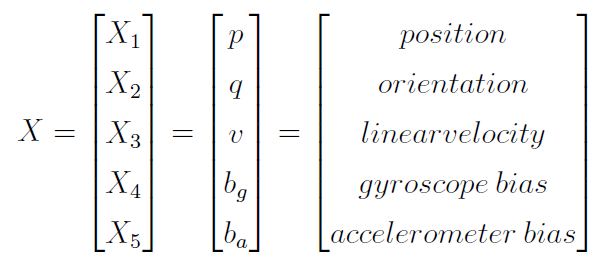
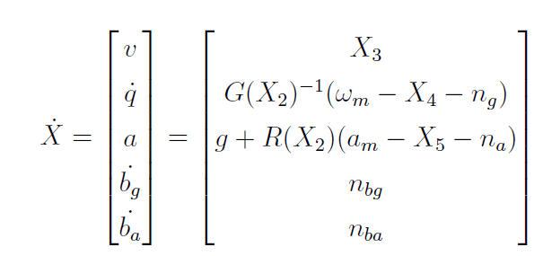
The state and its differential considered for EKF are,
All the state variables are considered to be represented in world frame. But IMU gives readings in body frame so rotation matrix is multiplied to obtain the readings in world frame.
Computer Vision
Pose
Here we estimate the pose of the UAV at all the times using the image data provided by the camera feed. A mat containing a matrix of 108 April Tags in (9 * 12) manner is laid on the ground and the MAV is driven such that the on board camera captures a few tags all the time. Now the top left corner of top left tag is considered as (0,0) point in the world frame. The dimensions of tags are denoted as shown in the image below,
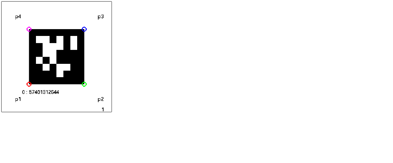
The next step is to use the known equation of projective transformation to calculate the transformation from the image frame to world frame. From this after making appropriate tansformations, we can get the required pose.
Optical Flow
Velocity is estimated by first calculating the optical flow using KLT image tracking technique. Later appropriate calculations are made to calculate linear and angular velocity of the MAV w.r.t world in the world frame. Firstly, we detect good points in a frame using FAST corner detector. Later we choose strongest 50 of those points to reduce the iterations. In the next frame, point tracker techniques are used to track the position of previously detected points in the current frame. The difference of these two sets of points from two frames is calculated and divided by delta_t to calculate the optical flow,
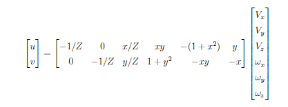
Now that we have the optical flow for every point of the image, we use the following equation to estimate the required linear and angular velocities of camera.
Resluts
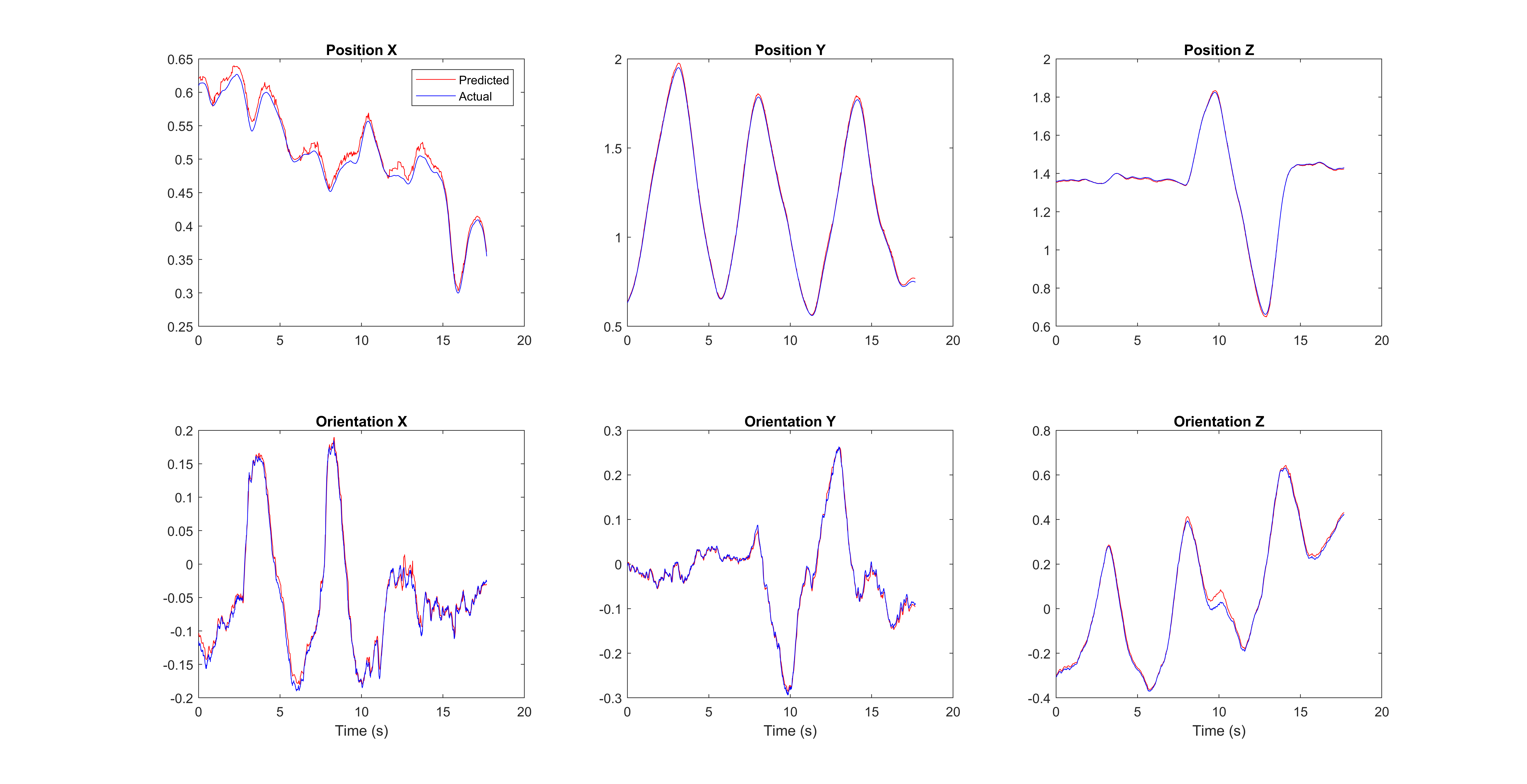
Since we have everything reqired by EKF, the following results are obtained.
 .
.

